The number of electric vehicles (EVs) and plug-in hybrid vehicles (PHEVs) on the road is growing.
In fact, the governor of California has set a goal for 1.5 million EVs on the road by 2025 — and that’s just one state in the U.S. Globally, sales could be much higher with projections in Europe reaching 3 million EV/PHEVs by 2020; authorities in China are setting an even loftier goal of having 5 million pluggable vehicles by 2020. With this growth, it only makes sense that there will also be a boom in the demand for vehicle charging stations.
Range anxiety is seen as one of the largest barriers to achieving consumer confidence in EVs. Plentiful and readily available charging stations will help relieve this anxiety and further increase EV popularity. A handful of free charging stations can already be seen at office complexes, parking structures, restaurants and shopping centers, but the need for “pay-to-charge” stations will increase, as will the need for more technology and communications in these systems. The technical demands for these systems will undoubtedly grow while system developers will be tasked with the challenge of increasing functionality while keeping the units small and uncomplicated.
Wireless charging and communications
Many of the pay-to-charge stations found in urban areas today look and operate similar to parking meters, except with the addition of a charging cable so users can plug in vehicles. There are three common types (or levels) of charging stations:
- Level 1 and Level 2 charging stations are “metered” AC power sources that utilize on-board charging functions of the EV.
- Level 3 includes DC “fast chargers.” These bypass vehicle power factor correction (PFC) and feed 400 VDCs to the batter charging stage.
While all power levels and stages are different, the need to meter the electricity usage and offer the capability to charge the customer a fee is the same. In “pay-to-charge” stations, it is also necessary to communicate with the back-end network for credit card charging, charging a mobile subscribers cellular phone plan, or even processing cash-based transactions. This functionality calls for the system to have a flexible architecture.
What does this mean for the technology used? Near-field communications (NFC), necessary for mobile payments, is a very short-range communications standard that acts in principle very closely to radio frequency (RF) identification. Each smartphone, or NFC-enabled device, has its own unique identifying code associated with a payment account. Ethernet, power-line communications (PLC) and Wi-Fi are necessary for payment processing, as well as for advanced metering and other control functions. Communications with the vehicle being charged are also required. Most EVs require communications with the charging station via CAN, RS232, Ethernet, PLC or with Pulse Width Modulation (PWM) signaling. So, how do the designers of these pay-to-charge stations keep designs relatively simple and cost effective while accomplishing all of the requirements necessary in these systems?
An easy solution to this challenge is to use an embedded controller or processor that offers NFC, PLC, Wi-Fi, CAN and 10/100 Ethernet communications along with the ability to handle the metering, housekeeping and power-stage control all in a single device. This way, developers can keep printed circuit board space and bill of materials costs to a minimum, while also integrating all vital communications and advanced protection functions into the system. An example of such an integrated embedded controller would be the C2000™ C28x + ARM® Cortex®-M3 based dual-core microcontrollers (MCUs) from Texas Instruments (TI). These MCUs can handle the power-stage control in additional to the necessary measurement, communications and interface requirements.
Serving as the foundation in metering systems are the analog interface and processing capabilities of the embedded controller. Using a device that contains this analog integration, designers can easily implement the required voltage and current monitoring required for single and three-phase AC measurements, as well as monitor output levels in the higher output DC-based systems.
Breaking down the design needs
We will divide the system into two sub-sections to simplify the diagrams presented:
1. The power supply that is being monitored
2. The low-voltage communications side of the system
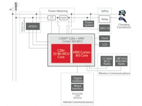
Since we are dealing with both low- and high-voltage systems, we must also consider the requirements for isolation between the high- and low-voltage systems. As previously mentioned, EV chargers are currently classified into three categories: Levels 1 and 2 (AC charging) and Level 3 (DC fast charging). In the Level 1 and 2 systems, the charging station architecture looks very similar to a standard metering application found in most smart grid applications, as shown in Figure 1. The meter is simply connected across a single- or three-phase AC source (common grid), and there are no power control stages within the system. It operates much the same as a residential meter, monitoring the flow of power through the system, with the added functions of communications both to the vehicle under charge and to the payment gateway. The system may also include safety monitoring and disconnects.
Both Level 1 and Level 2 chargers utilize the vehicles on-board charging system, which includes the power factor correction boost stage and the high-voltage DC charging circuit. Level-1 chargers are based on the standard 120/240VAC level, offering up to 16 amps of charge. Level 2 charging can utilize either 240VAC or 480V 3-phase AC, but both are limited to 32A. Again, in either Level 1 or Level 2 cases, the charger is simply acting as a metered interface between the utility grid and the vehicle being charged, with no energy-conversion stages.
DC fast-charging systems operate very differently, converting the AC mains voltage levels to a boosted DC level, capable of delivering up to 400 amps. While a Level 1 or 2 charger can charge the common EV in four to eight hours, the DC boost charger can offer the same level of charge in as little as 20 to 30 minutes. Although the power stages are quite different between Levels 1 and 2 when compared to Level 3, the metering application is common to all three as the metered input is always AC mains and ahead of any PFC stages.
Anthony Vaughan, Texas Instruments